Would you like to make this site your homepage? It's fast and easy...
Yes, Please make this my home page!
Transformers are one of the most powerful instruments in the field of AC electronics. More often then not the transformer is the first component to be used in AC circuit because its ability to radically change electrical values in a small area with a substantial cost and labor reduction. Although the transformer has many applications and has just as many shapes, this discussion is aimed in giving you an overall introduction to the transformer and details will come in the near future.
|
|
|
As the name implies, the transformers main function is to have an AC signal for the input and transform ether voltage or current to a desired level. Whether it be to increase or decrease voltage, increase or decrease current, or just have the efficiency level so low that the output is many times lower then the input. This is why in terms of electronics you will talk about stepping up or stepping down current or voltage. There will be more detail on this topic later on but for now lets got back to understanding how the transformer works.
Remember in the section called "the inductor" and in it how we talked about how flux lines are used to create voltage in the opposite direction of the current flow known as CEMF? Well the transformer is much like the inductor but instead of inducing a counter voltage on its self, the transformer translates the signal over to the second winding.
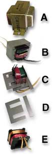
The basic transformer is constructed of two coils "primary and secondary" that are then wrapped around a soft iron core. Although the coils never electrically touch "transfer electrons", the primary coil does influence the secondary coil so that it looks as if there was current flowing through the transformer. You can see how the basic transformer is constructed in the illustration to the left.
The primary coil in transformer is the one that is connected directly to your wall socket or power source. That is, the negative terminal of your power outlet is connected to one end of the coil while the positive terminal of your wall outlet is connected to the other end of the coil. This is basically a loop that is used to create a strong magnetic field.
|
When the alternating current flows through the primary coil a field is created that is proportional to the strength of power. So when AC, that is Alternating Current it traveling through the coil an alternating magnetic field is created. This satisfies the conditions needed for power generation for the secondary coil. In upcoming sections like "Alternators and generators" we will learn why and how current is created form flux fields but for now lets get back to the transformer.
We know from previous chapters like "Current, voltage, and power" that voltage and static are very closely related, in fact static is what gives voltage its force even though voltage is just a measurement of static and electron pressure. We also know that static is the dominant force in any object because it binds atoms together to form all the elements in the universe. You should also know that magnetism is a property of static electricity, with this in mind we can then conclude that voltage, static, and magnetism are all related.
When these magnetic lines travel through the secondary coil electrons are ripped from their atoms and then replaced with electrons from Ground, returning alternation, or electrons that have completed the loop. Remember a circuit can not function without a completed loop or a reference to ground.
|
|
|
The illustration to the right is one of the transformers basic constructions. The Primary Coil (Pc) is directly connected to the AC power source. This AC alternation creates an alternating magnetic field that travels through the iron core and back to the source. These magnetic lines called "eddies, flux" are illustrated with the blue likns while the direction of the eddies/ flux is identified with arrows. These flux lines then travel through the iron core through the center of the Secondary Coil (Sc), this action generates power in the secondary coil. In generating power in the secondary coil we can make it seem as though there is a direct connection between the power input and power output. The advantage comes when we change aspects of what makes a good or bad power generator.
|
|
For example, eddies only travel on the surface of iron, we can improve power generation by making the core in layers instead of a solid chunk of a flux conductor. We can also increase or decrease the number of coil windings to make the transformer more or less efficient. In any case, the transformer gives us the ability to change output ratings by changing aspects to fit our needs.
Looking at the sliding arrows on all four corners you will see the numbers 5, 0, and -5, these numbers stand for the direction of the current, -5 is negative voltage, 0 is zero volts, 5 is positive volts. Notice that input to the primary coil is opposite as the out of the secondary coil, this will not always be the case but depending on how the transformer is created the output may be 180 ° out of phase with the input.
|
|
Home |
Contact us |
Our History |
Link to us |
Relations
A Passion Production ©opyright 2000