Would you like to make this site your homepage? It's fast and easy...
Yes, Please make this my home page!
The resistor is one of the most diverse and easiest of all the electrical components you will find in your average radio or TV set. This is because it has been around for many years and plays such a vital role that it will continue to in many new shapes and sizes to come. Today there are many different resistors in circulation, all of which will be explained shortly but for now lets go over some of the most important details.
The resistor is a component that has one purpose and that is to resist current and voltage by means of combining conductive material with a nonconductive one to form a substance that allows electrons to flow through its self but not as efficiently as a typical wire. The unit of measuring how much the resistor will oppose current is measured in ohms and to determine the outcome of the resistor we would use mathematical formulas known as ohms law.
There are three main types of resistors, which can then be broken down into other categories but lets first look at the three main types.
|
|
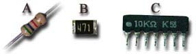
The carbon film resistor is composed up of a resistive material like graphite that is then cut into blocks or wrapped, or grafted in a desired way. For example, the length of the resistive material will determine how much resistance there will be while the width of the resistive material will determine what kind of power it can handle, the wider the more power it can handle. The schematic symbol can be seen in the picture to the right while the different types of carbon film resistors can be seen below. There are some three distinct types of carbon film resistors which as follows:
|  |
The standard film resistor (A)- a circular resistor with two pins extending from opposite sides or the barrel- shaped resistor.
The chip resistor (B)- this type of resistor was introduced in the late 80's to accommodate for the ever shrinking computer components where there can be up to 6 layers per circuit board.
The network resistor (C)- this type of resistor comes in (SIPP) form and can contain up to 12 resistors in a compact space that can not compare
|
|
|
|
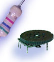
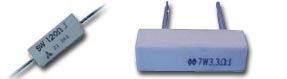
The most common wire wound resistor is composed up a fairly resistive wire wrapped around a ceramic cylinder and typically has a power range form 5 to 50 watts and is most often found in power supplies and amplifiers. It is common to find these components to heat up to levels that burns to the touch and is why they are made up of ceramic, a fire resistant material. The schematic symbol is the same of the carbon film resistor so it is also quite easy to remember.
|
|
The box to the right shows some typical wire wound resistors and more information can be found on each one by clicking on its picture.
|
|
|
|
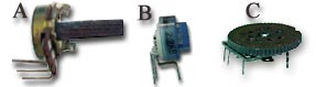
The variable resistor is a very important component that is found in many electrical for such things as tone and bass controls as well as volume. This is due to the fact that resistors can be joined together with other components to form filters for a desired levels. They can also be found in computer monitors for color or positioning as well as the dimming switch for your lamps.
This is done through digital to analog and analog to digital circuits, one great advantage to this is that you are able to turn a knob instead of typing a value in every time you want to change the tint or brightness.
|

|
The schematic for the variable resistor has stayed the same for quite some time and can be seen at the illustration to the upper right. As you see it looks somewhat like a typical resistor but is an arrow coming out from one side pointing to the center of the resistor. For more details on such questions like How does it work?, How do I use it?, and other such questions click on any illustration of your choice below.
|
|
|
|
Home |
Contact us |
Our History |
Link to us |
Relations
A Passion Production ©opyright 2000