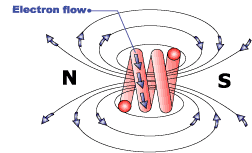
In the Intro to Flux and Magnetism you learned that when current flows through a conductor, a magnetic field surrounds the conductive wire. The more current traveling through the wire the greater the amount of flux lines will be present. What you didn't learn is what these lines of flux can generate voltage on surrounding conductors. It does this because as you learned before that flux lines, magnetism and static are all related, it is just that flux is a way of calculating magnetic lines and magnetism is a property of static.
As you know, static has two charges positive "protons" and negative "electrons" and when there is a greater amount of any particle then usual then the an equal amount of the opposite particles will be attracted to it. You also learned that particles that emitting same charges will repel each other and particles of the opposite charges will attract to each other. What does this have to do with the inductor?
Well the philosophy behind the inductor is that flux lines can generate voltage, this is used to alter waveforms in circuits where there is a presents of ripple current. Ripple current is current that is DC but it does not stay at one level, instead it is like water ripples.
Since flux lines are little more then static charges that can never intersect with flux lines of the same charge, as you increase current these lines of force start to extent further and further outward.
It turns out that if you have a field of surrounding a conductor "wire" and it comes in contact with another conductor "wire" then the flux lines will push electrons in a predictable direction. What you are actually doing is creating an Electromagnetic Force (EMF), also know as voltage in the opposite direction. However if there was only one coil which is the primary wire then the EMF is induced on its self, generating voltage in the opposite direction. Known as CEMF or Counter Electromagnetic Force or counter voltage this phenomenon is what makes the inductor possible.
|

|
As you increase current the magnetic fields start expand outward moving through near by coils. When this happens voltage is generated in the opposite direction making it harder and harder as you increase current flow. When current has reached its peak so has the inductors opposition to current flow because in order to generate voltage there must be movement in ether the magnetic fields or coil wires. Now if we were using a DC voltage source then this would be the end of the inductors use unless you were using it in an audio device or some alternating DC voltage application. In this situation you would pay attention to what happens when current declines as well as the current inclination. It is just like when voltage is introduced but instead of generating voltage on one direction, it generates it on the opposite direction making it look like the waveform is more oval than peaks and valleys.
See generators for more information on voltage and current generation.
When current has reached its peak the inductor stops working until there is a disruption in current flow like in the case of ripple current or in the case of audio applications or power supplies.
In audio application you would refer to these waves as frequencies or audio waves. In the case of speaker systems you would want to discriminate high frequencies from low frequencies. To do this you would use the inductor to filter out high frequencies, which is good when you are connecting a bass speaker. However if you were making a power supply you would not use the inductor to flatten down the AC current. What you would do is use a related device known as a transformer that steps down current or voltage. Next you would add a device known as a diode to make it so that current travels in only one direction but does not make the waveforms flat.
To flatten down the waveform you would use a device related to the inductor, known as the capacitor which is basically an inefficient battery that only holds a charge for fractions of a second but is perfect in an alternating DC circuit. This would be a good power source for analog radios but in the case of computer devices, you would want to further flatten the current with the inductor.
|
|
