Would you like to make this site your homepage? It's fast and easy...
Yes, Please make this my home page!
The inductor is one of the greatest electronic component to enter the electronic field, it utilizes AC waveforms to reduce current, the more current the more induced resistance there will be in the circuit. Through this discussion you will earn how to calculate the affects on the circuit that the inductor has as well as calculating inductance in different setup situations. You will almost never see an inductor in a computer system but you will se them in power supplies for all sorts of household electronics.
|
|
|
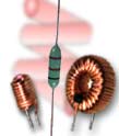
Here we have s set of five different inductors with distinct personalities.
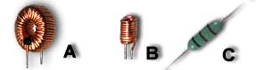
Inductor A is an inductor designed for high power environment, it has a ferrite core which gives it a greater inductance ability which makes it perfect for power supplies with a need for precise outputs.
|
Inductor B is an air core inductor which offers little inductance in a circuit but does have a thick coil, this is a good example of something that you would find in a TV set or computer monitor.
Inductor C is a device with an inductance rating specified on its outer rings. Although I will explain this inductor in much more detail later, you should also know what kind of devices you might find it in and why.
Due to a thin coil and compact size, it is only suitable for such devices such as hand held radios and such devices with low power consumption.
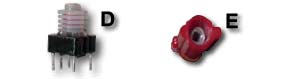
Inductor D is a device that has a variable core for precision tuning for such devices as radio frequency discriminating. As you might also have noticed, the coils are very thin few which means that the situation in where this device can be in are very limited.
Inductor E on the other hand is built much like inductor
|
|
D in the way that it has a variable core but the coil windings are much thicker and are able to withstand a greater amount of power. This device would be suitable for such devices like low consumption power-supplies.
|
|
The two inductors above look very much like the resistor and act the same in an AC circuit but if you were to place this circuit in a DC circuit you would quickly find out that the resistance will be in the range of 1 or 2 ohms instead of the printed value.
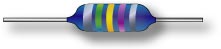
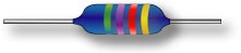
So lets try deciphering what this rings actually means shall we?
The top and bottom inductors are very much of the same family but how we calculate their values are somewhat different.
The top inductor has a thicker silver ting that indicates that it is of special interest, most likely it is for precise origin like military radio and other such devices. You will not see this type of inductor often and you would be lucky if you ever do.
The next ring is for the inductors first value, since the ring is green we can look at the chart and determine that the first value is 5.
|
| Color
|
Black
Brown
Red
Orange
Yellow
Green
Blue
Purple
Gray
White
None
Silver
Gold
|
|
|
|
|
|
Now this is where you have to be careful, the next ring is gold and when we look on the chart we can see that it is a decimal point.
With those two values we then add the next ring which is purple which is 7 so the inductance so far is 5.7but there is still more to do.
The last ring is the tolerance values, our tolerance is ±10% which means that it can be 10% above the specifies value or 10% below the specified value. In any situation we need not forget that the chart is in micro Henries so we would have 5.7µH or .0000057 Henries.
The lower inductor on the other hand is for much higher inductance values, to prove this lets figure out its inductance values.
The since the first ring is missing we know that there is no possibility of a gold ring which indicates a decimal point, so now the first ring is the first number in our equation.
With five recorded as our first number we now move on to the next ring but remembering that this is not a precision device means that we ill not be using any decimal points meaning that the next ring is our next number.
Adding the next number would produce a total of 57 but we have to now use the multiplier rating system since we are not using any decimal points. Since this is a red band we ill be looking on the chart to discover that have a red band means that we have to multiply our answer by 100. Now remembering that we are using a chart that is in the µH we need to correct our value. With the total of 7500 on a system of micro Henries we can conclude that we have a total of .0075 Henries or 7.5 mH
|
|
In a DC circuit there are three basic setups that inductors can be found and which are the parallel, series, and series parallel. The reason for having three different types is because inductors can be found in so many different values and some are cheaper then others.
The first is in a series circuit, this means that all the inductors and resistors are in the same circuit placed one after the other like a train and its cargo.
|
|
The equation for finding the total amount of Henries in a series circuit can be found using ohms law which states that you add charges that are in series. If we had a circuit with 3 inductors of 10µh, 13µh and 40µh the equation would be as follows:
10 + 13 + 40 = 63µh
|
Like with the series circuit the parallel circuit complies with ohms law which states that if a circuit is in parallel then you divide 1 by each component value and add the results up. Then 1 is divided by the sum of the components and the result is your total inductance. Lets say what we have 3 inductors of 10µh. 13µh and 40µh, the equation would be:
1/10 + 1/13 + 1/40 = .1 + .077 + .025= 2.02
1/ 2.02 = 4.95µh
|
|
|
|
For series parallel circuits what you will is find out if the last connection in the circuit is series or parallel. If the last connection is a series then you calculate all the inductors in parallel first then treat the circuit as a series circuit.
|
If the last connection in the circuit is in parallel then you calculate the total inductance of the series circuits then calculate the rest of the parallel circuit.
When you know your inductor values then you would calculate the time constant and apply that to the current, this will give you your waveform. Lets try it out shall we?
|
|
Home |
Contact us |
Our History |
Link to us |
Relations
A Passion Production ©opyright 2000